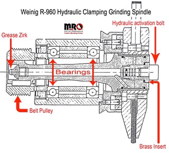
This educational article is for all profile knife grinder individuals; our goal is to provide a greater perception and understanding in the proper alignment of the Weinig Rondamat 960 grinding wheel spindle assembly. We will provide graphics and explanations that will be simple to understand and easy to accomplish.
Our history working with profile knife grinders goes back over thirty years, this commentary will benefit all those machine operators that currently utilize many models of Weinig profile grinders, we will focus primarily on the R960 with the option of hydraulic clamping grinding spindles.

Let us begin by stating that every profile grinder that Weinig manufactures has a specific blueprint and master assembly plan. The machinist building the machinery follow procedures precisely and effectively on every profile grinder, your grinding wheel spindle assembly is no different.
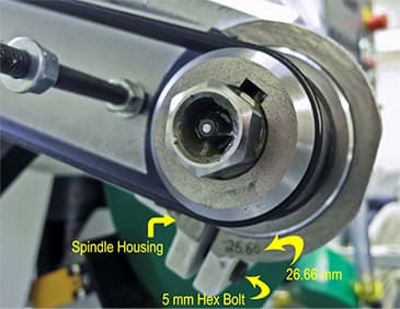
The precise axial (side-to-side) setting of the grinding wheel spindle assembly exists because the exact location of the grinding wheel dresser assembly located above and behind the grinding spindle, its function is to dress and shape vitrified grinding wheels by way of a diamond dresser . The grinding wheel dresser unit, which remains secured to the machine by two eight mm hex bolts, is pinned in position to the main casting to prevent movement. The grinding wheel spindle, also installed on the main casting, secured in position by two five mm hex bolts.

Every profile grinder built has a similar but different final axial setting number on the grinding wheel spindle, proper alignment of the grinding spindle will assure correct centering while dressing and shaping a grinding wheel, it will also aid in axial constant alignment , refer to this educational article located on our website.
The exact locating position of the spindle assembly is punch stamped into the casting of the casted spindle housing in millimeters, (example 26.66). To be able to view the exact position of the spindle assemble, remove the belt guard that covers and protects the pulley’s and belt, (see image above) it may require you to remove some rust buildup, use some very fine sandpaper or scotch bright pad, enabling you to view the numbers.
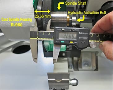
That number inscribed in the casting represents the distance from the casting face to the edge of the spindle flange, where the grinding wheel hub meets the spindle assembly, (see picture below).

If you have not moved or replaced your grinding wheel spindle assembly then you probably need to do nothing. If you have moved your grinding wheel spindle for cleaning, maintenance, or replacement you should position the spindle assembly back to factory setting stamped on casting in order not to disrupt the proper functioning and alignment of the grinding wheel-dressing unit.
One final reminder, make sure you replace all safety guards removed during calibration before resuming a normal production operation, everyone’s safety should be of the highest concerns.
We hope you have obtained another piece of valuable information on your career’s journey, if you have any further questions or comments concerning the process or steps explained in alignment of the Weinig R960 grinding spindle, please feel free to contact us.


